How I Built Procedural Tracks and Vertical Loops in Godot
How I Built Procedural Tracks and Vertical Loops in Godot
I’ve been working on an arcade racing game with a level editor for making and sharing tracks!
I’ve had a few personal projects going. This track editor ate most of my free time, so here is what I learned from it.
The art is placeholder until I finish the extrusion math.
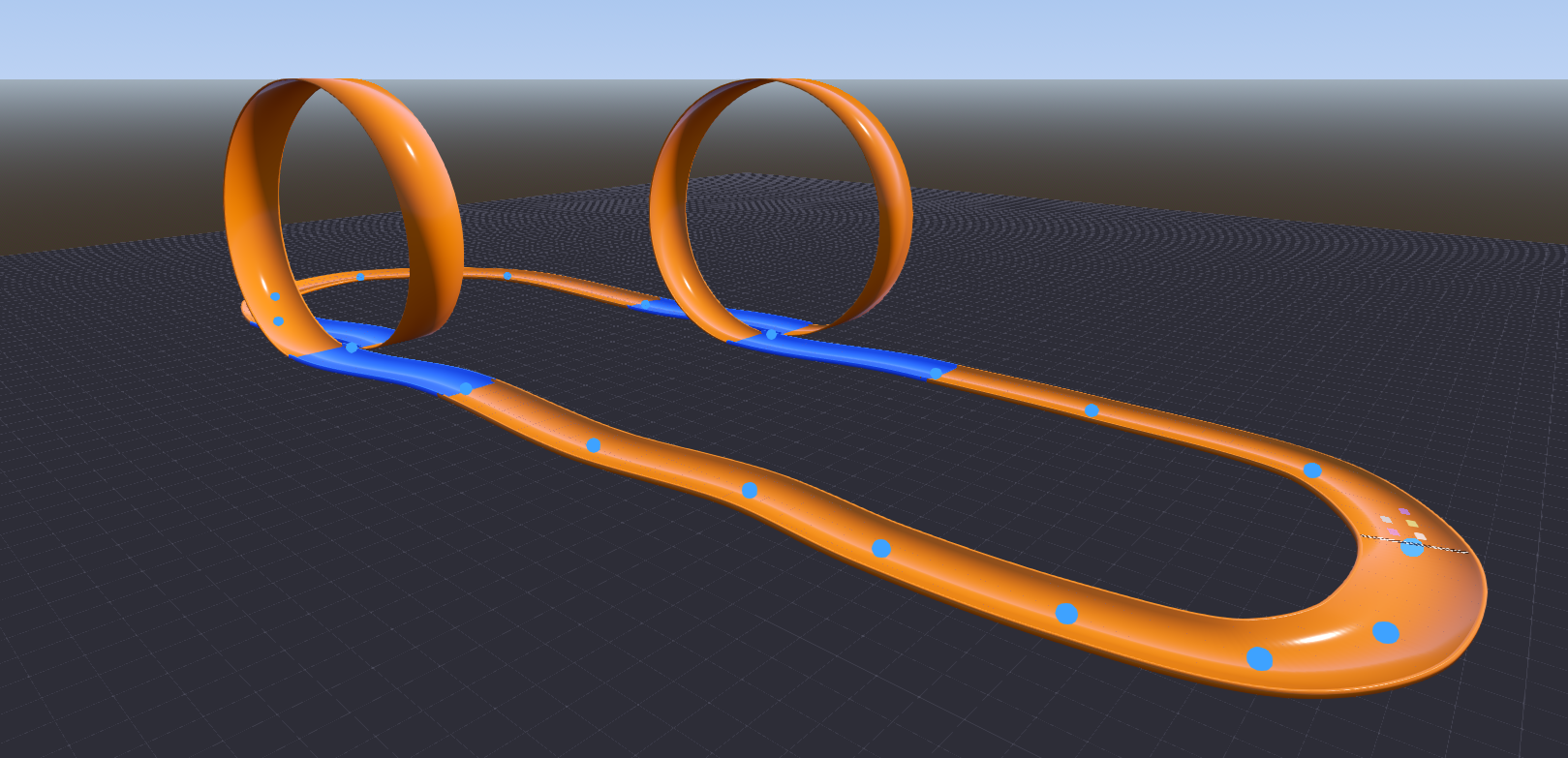
Now I realize this doesn’t look like much with very little context, but this is what hours of work looks like.
Originally I wanted to create an arcade racing game that uses blendshapes tied to physics (lean left to deform a blendshape, squash, stretch, etc). More on that some other time. For now I just wanted to yap about how I made the tracks and loops in Godot 4.6.
I’ve shelved it for now but I learned a ton about 3D math and Godot and I may come back if I ever want to iterate on this.
At first I was going to model individual track pieces but I decided to go with another solution after playing the F-Zero X Expansion for the N64DD (the track creator specifically). I really liked how quickly you were able to lay down a track using points on a grid so I (mistakenly) thought this would be a fun way to approach custom track creation.
Here is how I built the track meshes from splines.
Drawing the Path: Splines
A spline is just a curve through a set of points. I went with a Catmull-Rom spline instead of Godot’s usual Bezier curves because it passes through every point I place, with no handles to fiddle with.
To get the track direction at any spot, I compare the points before and after
it. For points P0 through P3, this gives me the position between P1 and P2 as
t moves from 0 to 1:
P(t) = 0.5 * (
    (2 * P1) +
    (-P0 + P2) * t +
    (2 * P0 - 5 * P1 + 4 * P2 - P3) * t^2 +
    (-P0 + 3 * P1 - 3 * P2 + P3) * t^3
)
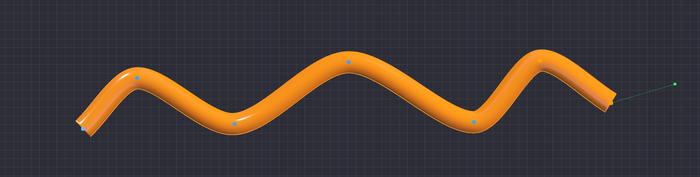
Building the Road: CSG Extrusion
For the road itself, I use Godot’s CSGPolygon3D. I draw the road’s cross
section as a flat 2D shape, then sweep it along the spline. That gives me the
road and curbs without modeling every piece by hand.
# Required by CSGPolygon3D to determine the shape of the 3D extrusion
func _build_profile() -> PackedVector2Array:
    return PackedVector2Array([
        Vector2(-HALF_WIDTH, 0.0),
        Vector2(-HALF_WIDTH, LIP_HEIGHT),
        Vector2(-HALF_WIDTH - LIP_WIDTH, LIP_HEIGHT),
        Vector2(-HALF_WIDTH - LIP_WIDTH, -LIP_UNDERHANG),
        Vector2(HALF_WIDTH + LIP_WIDTH, -LIP_UNDERHANG),
        Vector2(HALF_WIDTH + LIP_WIDTH, LIP_HEIGHT),
        Vector2(HALF_WIDTH, LIP_HEIGHT),
        Vector2(HALF_WIDTH, 0.0)
    ])
The Problem with Vertical Loops
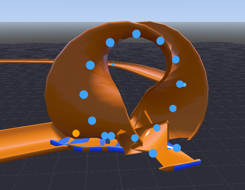
This works for flat tracks and hills. A full vertical loop wrecks it.
The path follower needs an “up” direction. At the top of the loop, forward and up line up, the math loses a clean direction, and the mesh twists itself into some sentient eldritch being.
Fixing Loops with Math
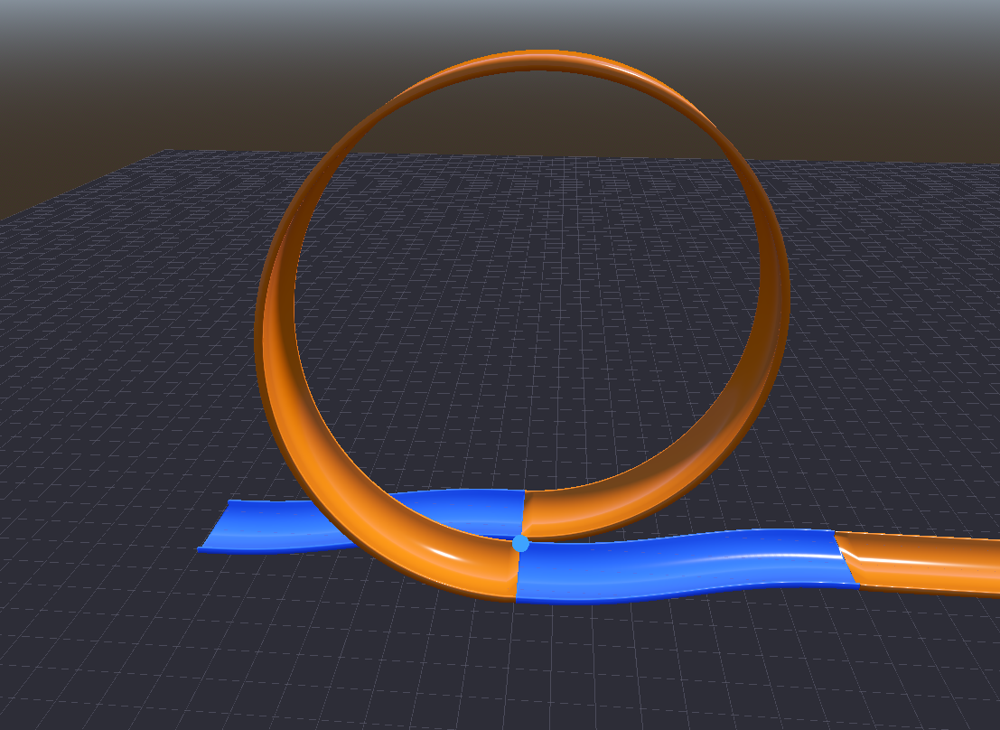
I gave up on CSG for the loops and made those meshes myself. I treat each loop like a sideways cylinder and slide it a little to the side as it goes around, so the exit does not crash into the entrance.
A smootherstep curve keeps that shift from jerking at either end:
smootherstep(t) = 6 * t^5 - 15 * t^4 + 10 * t^3
Then I calculate X, Y, and Z from one t value running from the start of the
loop to the end:
X(t) = HalfOffset - (TotalOffset * smootherstep(t))
Y(t) = Radius * (1 - cos(2 * PI * t))
Z(t) = Radius * sin(2 * PI * t)
For the loop, “up” points toward the center of the circle instead of world up. I get forward from the derivative, then rebuild the other directions from those two. Since the sideways shift also changes over the loop, I need the derivative of smootherstep too:
smootherstep_deriv(t) = 30 * t^4 - 60 * t^3 + 30 * t^2
# Avoids spline tangent errors by determining direction analytically
var dpx := -LATERAL_OFFSET * _smootherstep_deriv(t)
var dpy := radius * TAU * sin(angle)
var dpz := radius * TAU * cos(angle)
var tangent := Vector3(dpx, dpy, dpz).normalized()

# Prevents gimbal lock at the loop apex by using a centripetal reference
var up := Vector3(0.0, radius - py, -pz).normalized()

var right := tangent.cross(up).normalized()
up = right.cross(tangent).normalized()
Constructing the Mesh
I use Godot’s SurfaceTool to turn those points into triangles:
var st := SurfaceTool.new()
st.begin(Mesh.PRIMITIVE_TRIANGLES)

for i in LOOP_SEGMENTS:
    for j in pcount:
        var jn := (j + 1) % pcount
        var a := sections[i][j]
        var b := sections[i][jn]
        var c := sections[i + 1][j]
        var d := sections[i + 1][jn]

        st.add_vertex(a)
        st.add_vertex(b)
        st.add_vertex(d)
        st.add_vertex(a)
        st.add_vertex(d)
        st.add_vertex(c)

st.generate_normals()
var mesh := st.commit()
Curb Height
The tall curbs from the normal track became a problem in loops. If a wheel catches one while the car is upside down, it can kick the car off the track. I shrink the curb height for loop sections.
# Reduces lip height to prevent vehicles from catching their wheels on the inside of the loop
var lh := SplineRoad.LIP_HEIGHT * 0.3
var lu := SplineRoad.LIP_UNDERHANG * 0.3
Once the loop mesh is built, I connect the regular CSG track to its entrance and exit. That skips a lot of ugly details, but hopefully it helps someone.
If you made it this far, you are worthy enough to see my ugly work-in-progress race-track editor for this experiment.
Written for Godot 4.6